⚙️ Pseudocode Syntax Reference
The pseudocode tool in InfoRapid KnowledgeBase Builder allows you to generate flowcharts and decision trees fully automatically from a simple, readable text syntax. Instead of having to draw and connect every element manually, you simply write the logic as text.
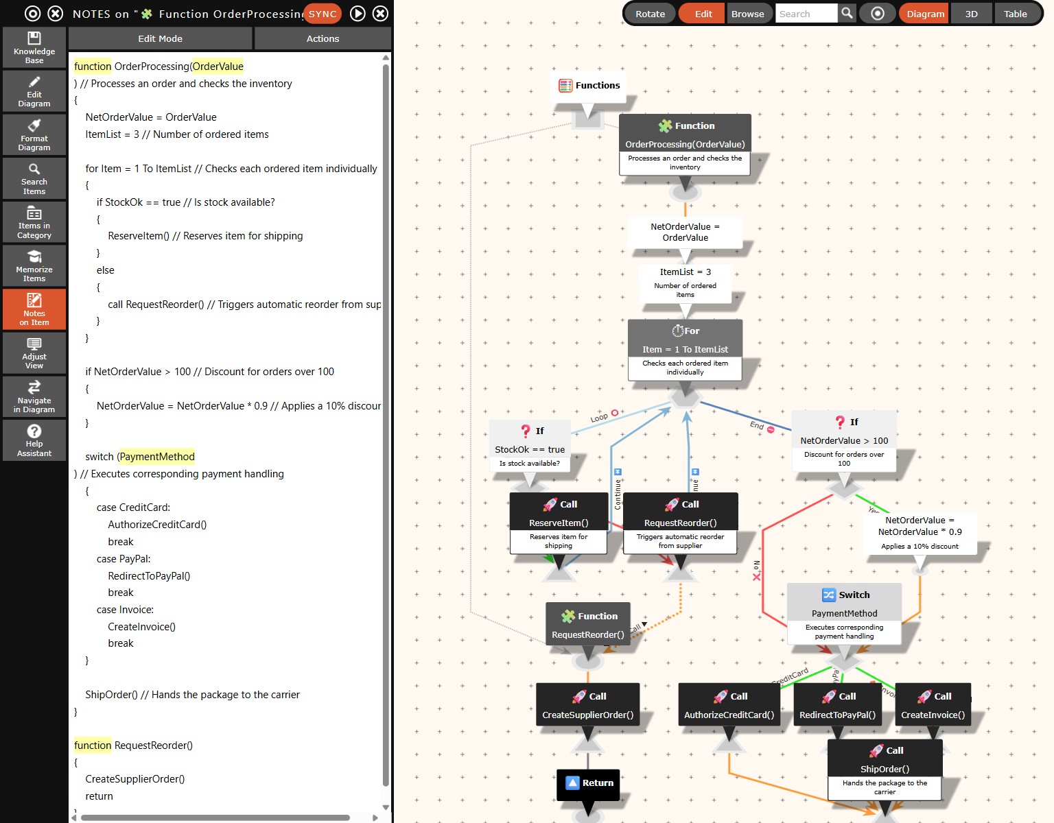
1. Basic Structure & Comments
- Line Endings: Statements do not require a trailing semicolon (
;). Each statement is written on a new line. - Comments: Are initiated with
//and extend to the end of the line. Comments are automatically imported as node descriptions (tooltips) into the diagram. - Example:
A = A - 2 // Calculates the new value of Acreates a command node labeledA = A - 2with the tooltip text"Calculates the new value of A".
2. Functions
A flowchart can be divided into multiple functions. Each function begins with the keyword function, followed by the name of the function, optional parameters in parentheses, and a block enclosed in curly braces { }.
function MyFunction(Parameter1) // Description of the function
{
    // Content of the function
    return
}
3. Subroutine Calls (Functions)
Calling another function is declared with the keyword call. This creates a special "call" node (in the shape of an upward-pointing triangle) in the diagram.
call MyFunction(5) // Executes the sub-function
4. Control Structures: Branches
If-Else
Creates a conditional branch (diamond shape). The connections for the "Yes" and "No" branches are automatically labeled according to the condition.
if A > 0 // Is A positive?
{
    A = A - 2 // Decrease A
}
else
{
    B = B + 2 // Increase B
}
Multiple Branching (Switch-Case)
Creates a branch based on the value of a variable or expression. Each case edge is labeled with the name of the respective case. Each case must be ended with break.
switch (PaymentMethod) // Select payment processing
{
    case CreditCard:
        AuthorizeCreditCard()
        break
    case PayPal:
        RedirectToPayPal()
        break
}
5. Control Structures: Loops
While Loop
A pre-tested loop. The condition is checked before the loop execution. The loop node receives a hexagonal shape.
while A > 0 // Repeat as long as A is greater than 0
{
    A = A - 1
}
Do-While Loop
A post-tested loop. The loop body is executed at least once before the condition is checked at the end. The start node receives a parallelogram shape.
do
{
    A = A + 1
}
while (A < 100) // Check if the limit is reached
For Loop
A loop over a range of numbers. Supports the English keywords To and Step.
for N = 0 To 100 Step 3 // Count in steps of 3 from 0 to 100
{
    ProcessValue(N)
}
6. Flow Control
- break: Terminates the current loop or switch block.
- continue: Jumps directly to the next loop iteration.
- return: Ends the execution of the current function and returns to the caller. This creates a circular "return" node in the diagram.